February 10, 2024
I was watching a YouTube video from Dave's Garage and saw an amazing lamp in the background that looked like it was shooting fire and flames. I knew I wanted to build something like this but the only information I could find on Dave's site was that he bought the lamp at Home Depot and modified it. I thought I could do the same so I mail ordered the lamp from Home Depot and immediately began to think about how I could rebuild it. I wanted the lamp to be able to display numerous beautiful, colorful patterns in addition to the fire display I first saw. After some serious contemplation I determined that the rebuild would require new LEDs (a total of 131), some electronics, some 3D printed pieces and a lot of patience.
The first step in the rebuild process was to completely tear the lamp apart which is exactly what I did. Kind of scary after just spending about $140 buying it. The stock lamp had white LEDs that could only be turned off and on and/or dimmed via a foot switch. I ripped out the white LED strips and replaced them with WS2812B LED strips/strands which would provide the color I needed. I also cut off the power supply and foot switch that came with the lamp as they weren't needed any longer.
I wanted my rebuilt lamp to be motion and time activated and I wanted the ability to switch between these two modes. So I purchased a WEMOS D1 Mini ESP32 to control the lamp, a AM312 PIR motion sensor to detect motion and a 10 amp 5 volt power supply to power it all. I already had a small momentary push button switch for mode switching.
The finished lamp operates in one of two modes: "motion activated" which only triggers the lamp when motion is detected and what I call "time activated" which is that in addition to being triggered by motion, the lamp turns on by itself periodically and displays a colorful pattern even with no motion present. The lamp software that I have written and that I am still working on has seven built in colorful display patterns that are selected randomly whenever the lamp is triggered. I will probably add many more unique patterns as time goes on. The lamp software uses the FastLED library for controlling the LED strands.
The WEMOS D1 Mini ESP32 controls the operation of the lamp and goes into deep sleep between lamp activations. The PIR motion sensor wakes the processor when motion is detected. In addition, when the lamp is running in time activation mode the ESP32 wakes itself periodically. The current activation mode is stored in the ESP32's EEPROM so it survives loss of power. There is a simple procedure for changing the activation mode. Holding the mode push button switch down while power is applied to the lamp toggles the mode. If the lamp was in motion activated mode it will toggle to time activated mode and vise versa.
 |
Here is a picture of the stock
Home Depot lamp. After the lamp rebuild, the lamp
looks basically the same but operates much
differently. The patterns that the rebuilt lamp displays are not only beautiful to look at but the lamp itself is a beautiful piece of modern decor. |
 |
|
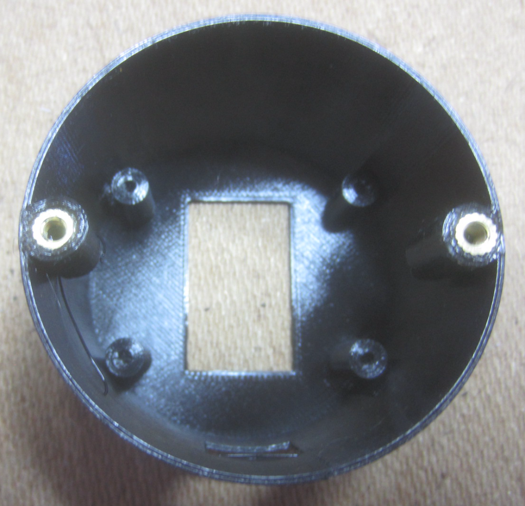 |
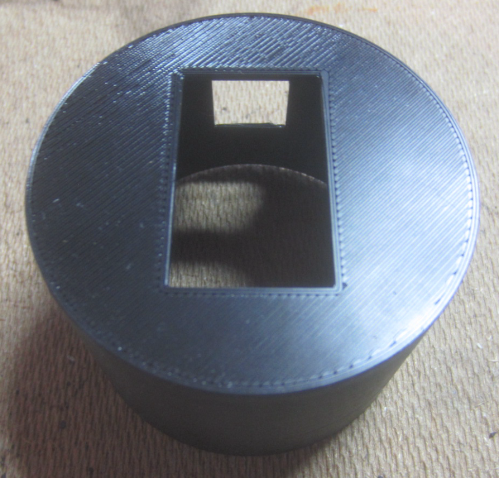
Inside the housing you can see
four posts for mounting the ESP32 module carrier and
the two posts with embedded nuts for mounting the
finished housing to the lamp's base. This housing was
3D printed in this orientation so no supports of any
kind were required. |
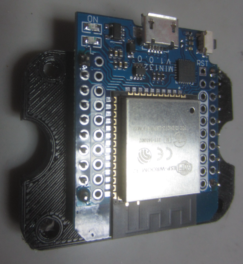 |
This is the WEMOS D1 Mini ESP32
module mounted onto the 3D printed support. The four
holes in the corners of the support mate with the
posts in the image above. |
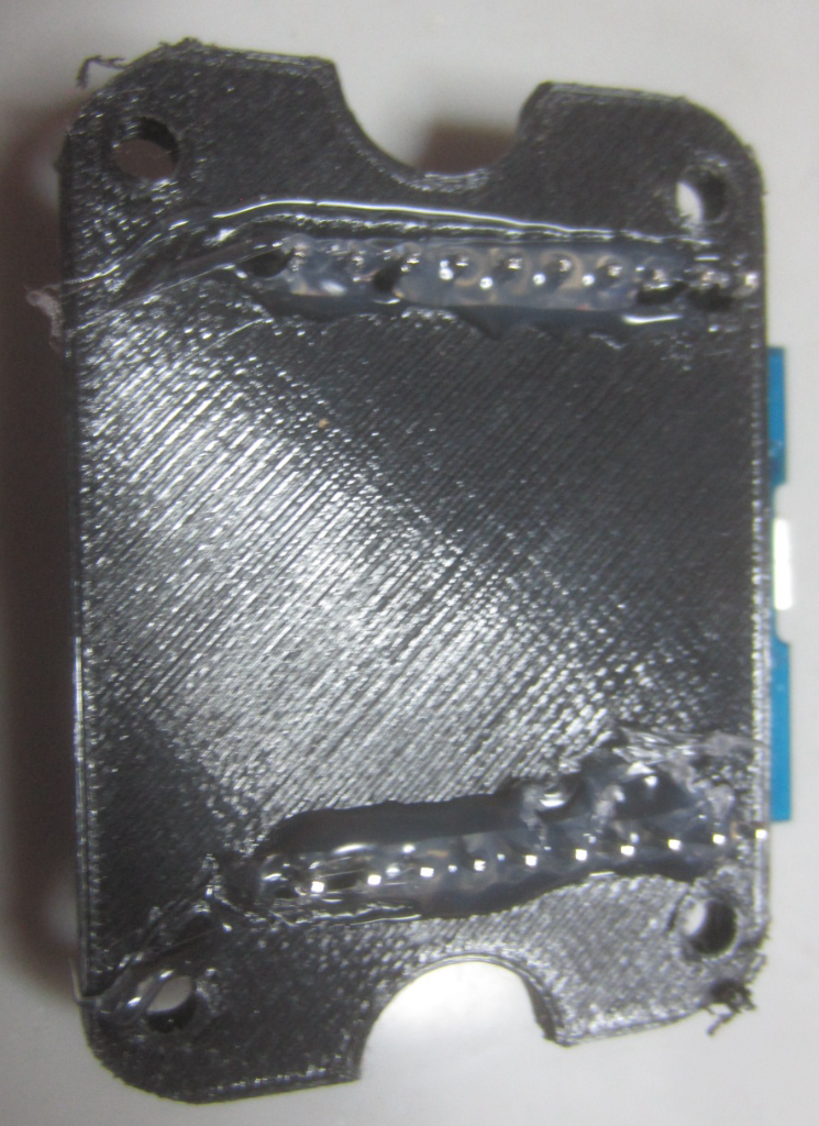 |
I hot glued the ESP32 module to
the 3D printed support. The ESP32 had to be firmly
mounted because of inserting and removing a USB
programming cable over and over. The half circle
cutouts on the sides of the support are necessary to
allow this module to slide in between the housing
mounting posts. |
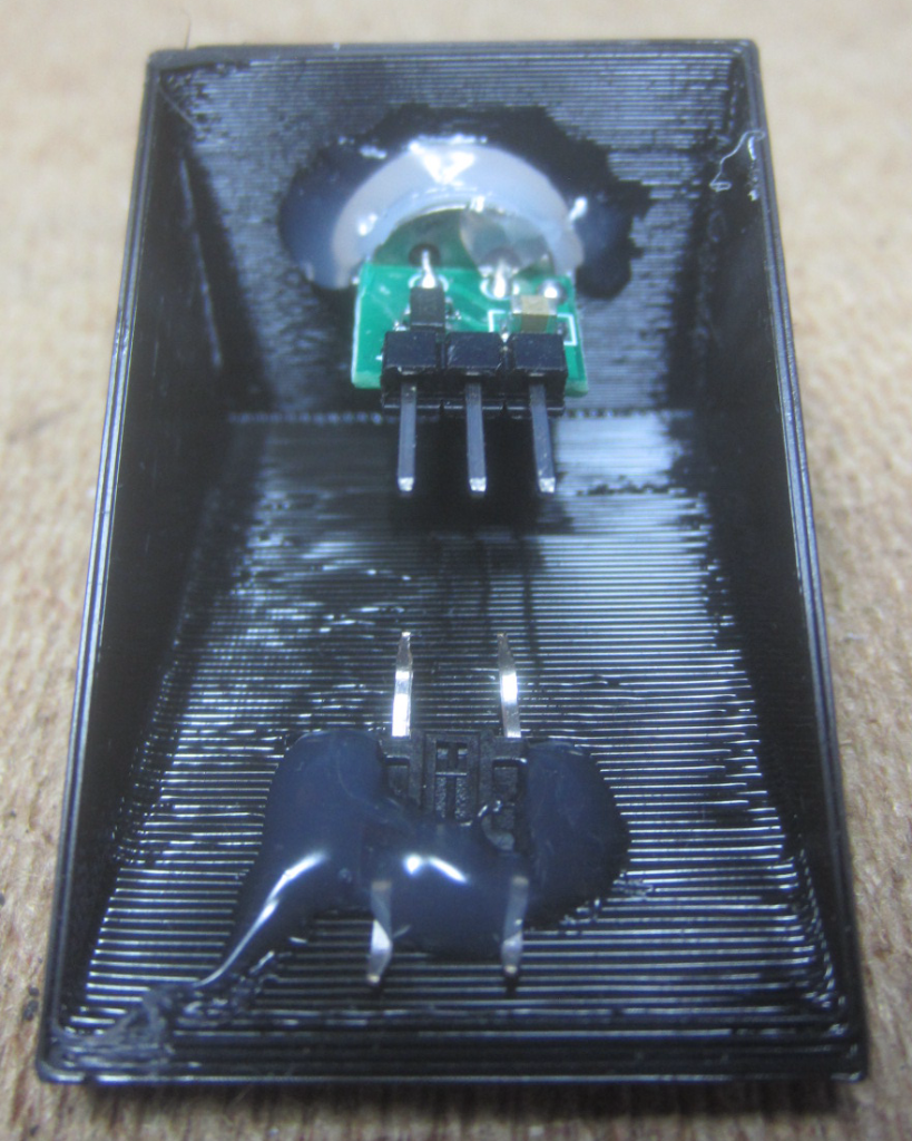 |
3D printed PIR motion sensor and
mode switch support with the components hot glued in. |
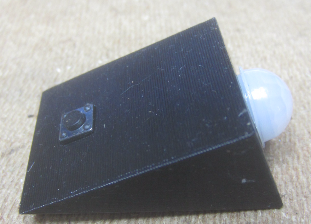 |
PIR support with mode push button
switch. The PIR sensor is pitched upward at a 30
degree angle because it will be mounted on the base of
the lamp and needs to detect motion above the floor. |
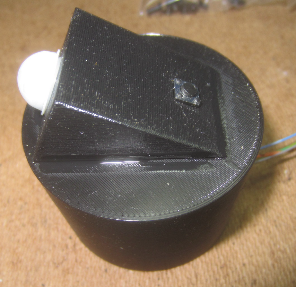 |
PIR support super glued to
housing. Wires coming out of the bottom will be
connected to the ESP32 and LED strands. |
 |
WEMOS D1 Mini ESP32 with support
plate screwed into the housing. The USB cutout shown
on the right of the housing allows a USB cable to be
plugged in for programming. This USB cable access hole
faces the back of the lamp so it is never seen. A USB
cable connection is only needed for programming and is
never needed during normal operation of the lamp. |
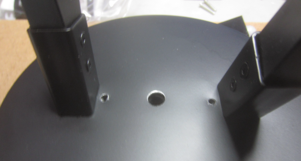 |
Three holes needed to be drilled
into the base of the lamp. The two outer holes are for
mounting the PIR housing and the center hole is for
wiring to pass between the LED strands in each arm of
the lamp and the ESP32. |
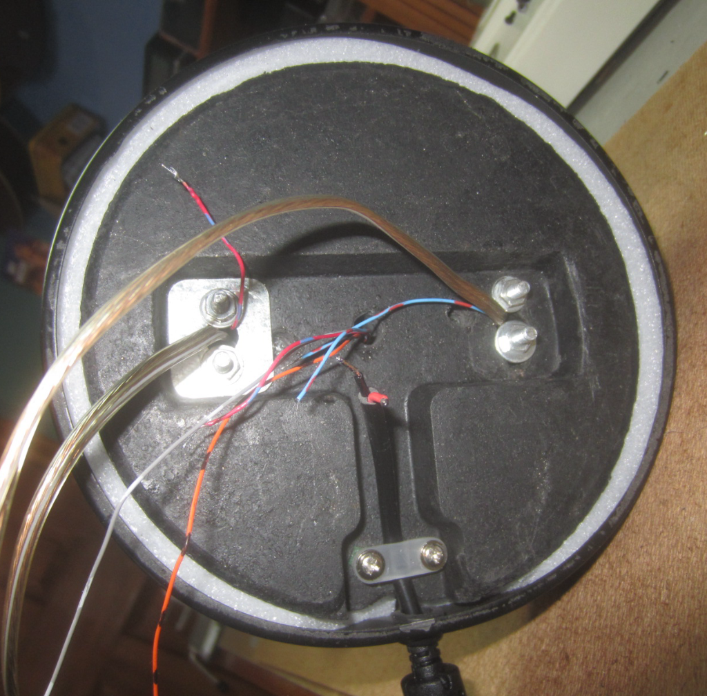 |
Wiring in the base of the lamp.
Wiring on both the left and right sides of the base go
to the LED strands in each arm of the lamp. Arm wiring
consists of +5V, Ground and a DIn signal. Wiring in
the center of the base goes to the ESP32, the PIR
sensor and the mode push button switch. The wiring
from the bottom is from the 5V 10 amp (probably
overkill) power supply. |
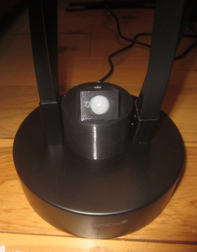 |
Here is the completely assembled
PIR sensor housing mounted between the two arms of the
lamp. You can see why the PIR sensor needed to be
angled upward. |
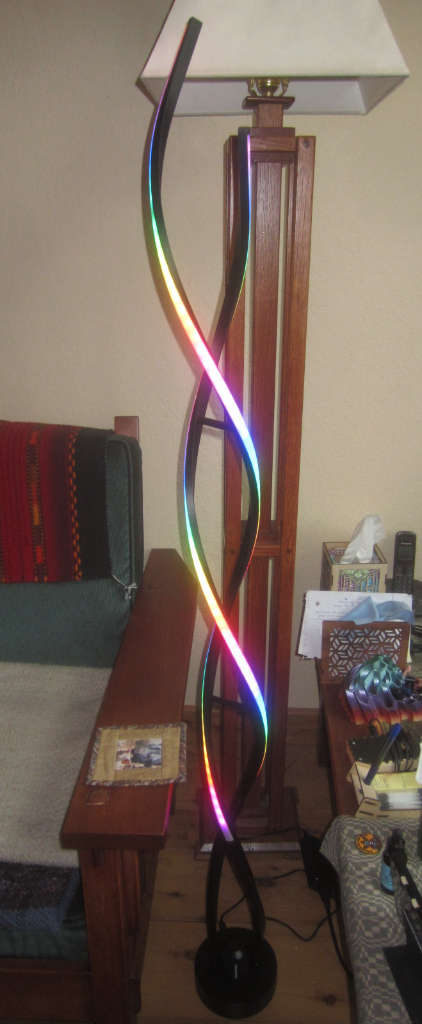 |
Here is a picture of the finished
lamp in operation. Each of the seven built in patterns
are beautiful to watch. When the lamp is triggered
(with the current software) the displayed pattern will
last for 90 seconds before turning off and putting the
ESP32 to sleep. In time activation mode, the lamp will
wake itself and display a random pattern every four
minutes. |
Questions and comments to me Craig at: calhjh@gmail.com