The Crystal Palace Page


Home                               Craigs Pages                               Heathers Pages


Nov 16, 2014

The Crystal Palace device came about quiet out of the blue (so to speak). I had written an article for Nuts and Volts magazine (to be published sometime in 2015) entitled "Controlling LEDs with A Micro Controller" which described how multiplexing can be used to drive an 8x8 RGB LED matrix with a Teensy 3.1 micro controller. The second article, also for Nuts and Volts,  "Using Serial Bluetooth with a Micro Controller" extended the design presented in the first article by adding an HC-05 Bluetooth module which allowed the LED matrix to be controlled remotely via a computer, phone or tablet. As I finished the second article I was faced with a quandary. I had the LED matrix being successfully controlled remotely via Bluetooth and I was really quite pleased with the result. I could run some very interesting and colorful patterns, I could use the device as a mood light and I could even display scrolling text messages. What was I to do? Tear down the breadboard I had just finished building to scavenge the parts to use else where or should I try and figure out a use for the finished product. I, of course, choose the latter and the Crystal Palace was born.

The videos below show the Crystal Palace in operation.

Please ignore the clicking sound track. It was caused by my camera trying to continually adjust to the variable lighting conditions produced by the Crystal Palace during filming.


The finished hardware for the Crystal Palace.

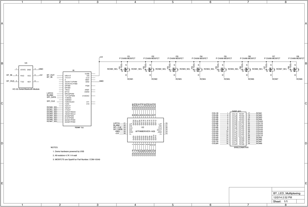
Eight P channel FET row drivers are positioned along the left of the 8x8 RGB LED Matrix.

Note that the 8x8 matrix contains 64 RGB LEDs which equates to 192 individual LEDs that are controlled by this hardware.

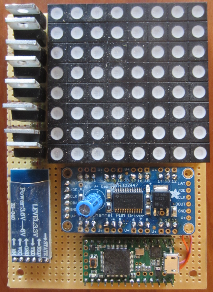
The HC-05 Bluetooth module is on the left, the Adafruit 24 Channel PWM driver is in the middle and the Teensy 3.1 micro controller is at the bottom.

All of the components were connected  together using point to point wiring on the bottom of the breadboard.

The Crystal Palace in its finished, packaged form.

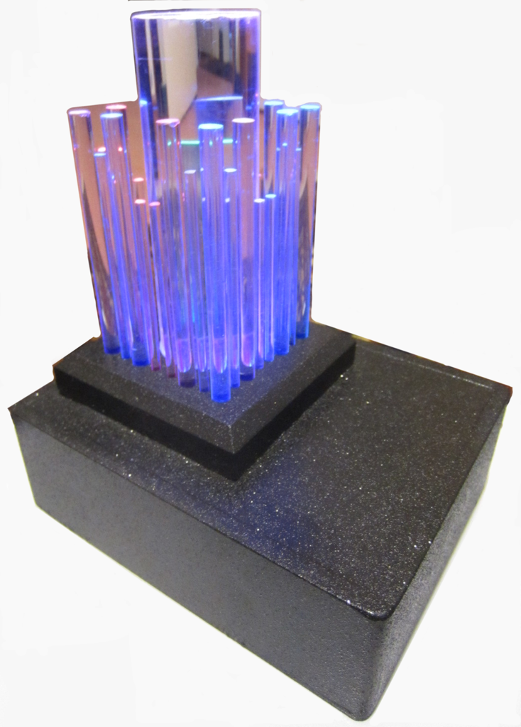
Three different diameters of acrylic rods are used. The rods pass through their wooden support to rest directly on the LED matrix mounted horizontally within  the case.

The rods convey the light from the LED matrix up through themselves lighting their ends brightly.

The case is made from 1/4" MDF and painted with sparkle black paint.

A USB cable enters the case from the back so it is not visible here. The cable plugs onto the Teensy micro controller which then powers all of the components. A USB power module producing 5 VDC at 1 amp powers the Crystal Palace.

A picture of the Crystal Palace taken in the dark. The varying lengths of the acrylic rods makes the colors dance up and down as it moves from side to side.

Another picture of the Crystal Palace taken in the dark.

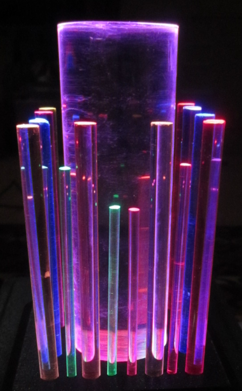
Still imagery just doesn't show how pretty the Crystal Palace really is.

Schematic of the Crystal Palace


The Crystal Palace firmware is available here. Of course since you have the source code you can easily extend what I have done by adding your own display patterns and new modes of operation.

Have Fun !


Home                               Craigs Pages                               Heathers Pages