The two connectors surrounding the TLC5940 chips are for attaching the Seeed Studio LED cube.
The wires running off the board connect to the power supply, the on/off switch and the small condenser microphone.
|
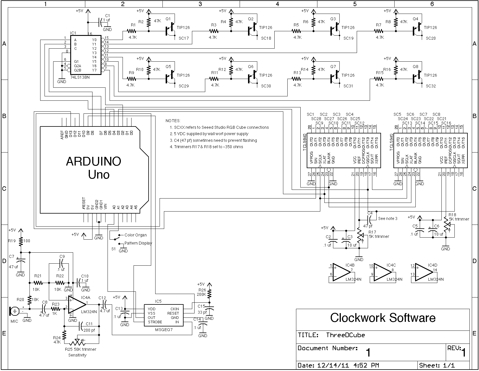
Since this was a one off project I decided
to build it on a piece of pref board instead of trying to design a PCB.
The analog circuitry is on the right with the blue trimmer being the
mic preamp gain adjustment. The long vertical chips on the left are the
TLC5940 LED drivers and the two trimmers on the very left are for
setting the maximum LED current. In total there are eight power
transistors: four on top and four on the bottom. From left to right the
chips are: TLC5940, TLC5940, 74LS138, MSGEQ7 and the LM324. The two connectors surrounding the TLC5940 chips are for attaching the Seeed Studio LED cube. |
|
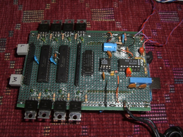
The underside of the assembly is quite the
rats nest since I used point to point wiring. The blue circuit board on
the right is the underside of the Arduino Uno board. |
|
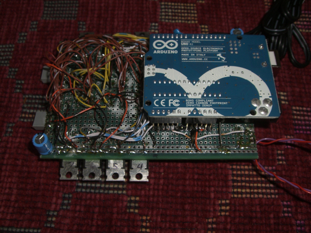
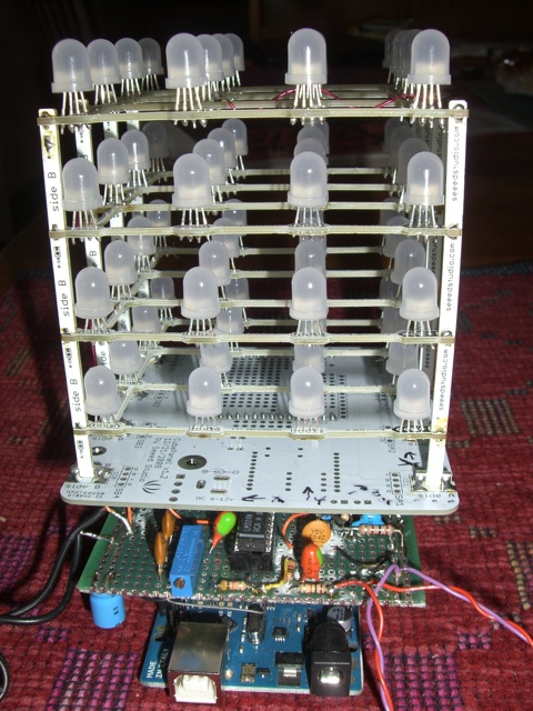
Here you can see the three subassemblies
mated together. On top is the Seeed Studio's LED cube, the middle is
the board containing the custom circuitry I designed (shown above) and
the bottom
is the Arduino Uno. The wires running off the board connect to the power supply, the on/off switch and the small condenser microphone. |
|
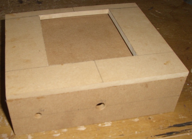
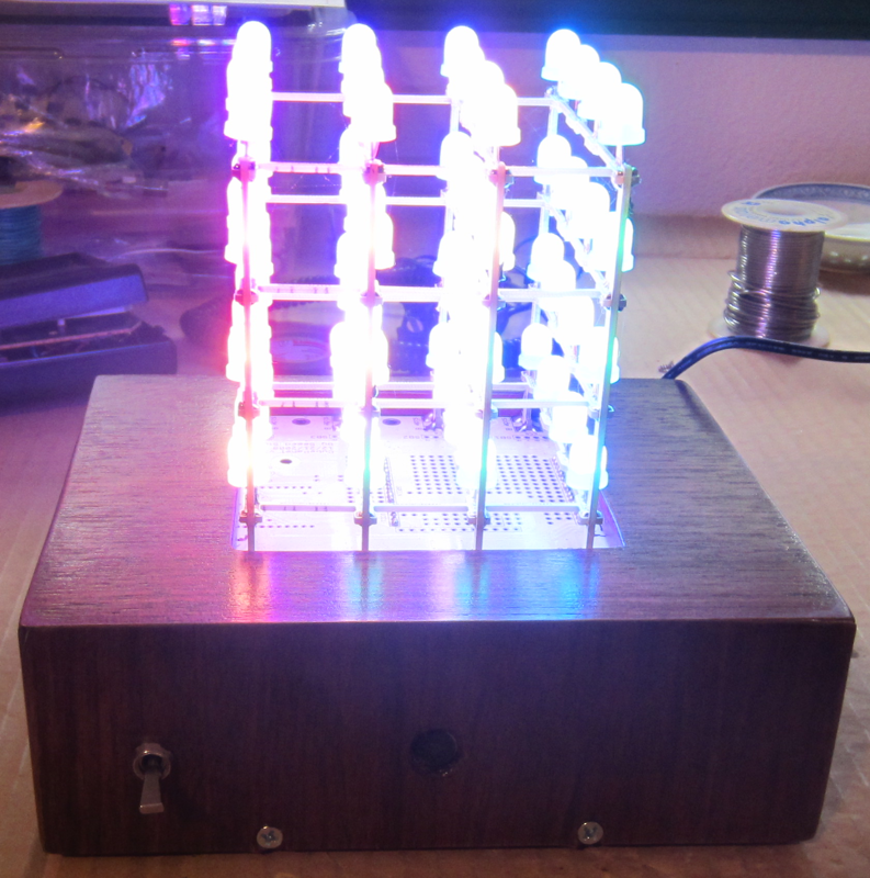
I built the enclosure out of 1/4" MDF as I plan to paint or
veneer it when the weather gets warmer. |
|
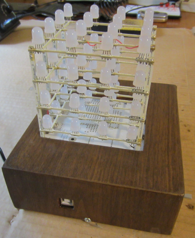
Here is the electronics mated to the enclosure. The power
switch is at the left and the microphone is located in the hole in the
center of the front panel. The wire for the wall wort power supply
comes out the back. |
|
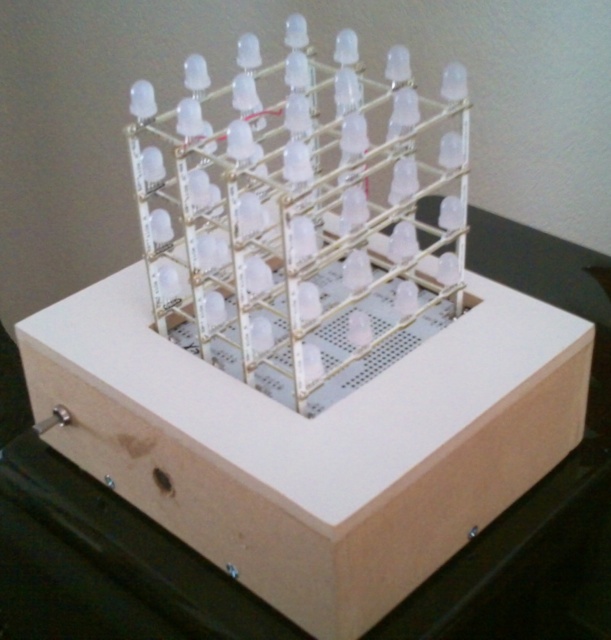
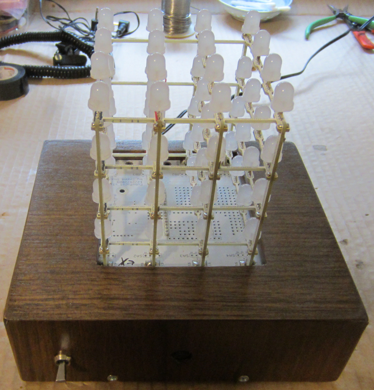
Here
is the base after being
veneered. I guess it turned out pretty good for my first veneering
attempt ever. |
|
Another
view of the veneered
base. |
|
Here
is a view with the cube lit
up. The bright RGB LEDs were just to much for the camera but at least
you can see the veneered base. |
|
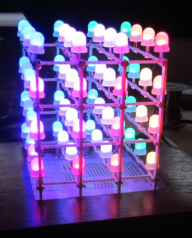
Here
is a better exposure of the
cube lit up. |