NeoPixel LED NTP Clock Page


Home                               Craigs Pages                               Heathers Pages

June 2016
Did the the world really need yet another digital clock running on a micro controller? I didn't think so until daylight savings time changed again and I had to go around my house and change the time on many of my clocks. Not only that, one of the batteries in a clock had died so I had to replace the battery and then set the time and date again. In another of my clocks the quartz movement seems to gain time slowly so I never really know the time accurately. I started thinking about what a pain this all was so I decided to build a clock that:

1. Was extremely simple to make
2. Didn't need backup batteries or batteries of any kind
3. Was always accurate
4. Dealt with daylight savings time automatically by itself

In other words I wanted to build a clock that needed zero maintenance on my part and that would always display the time and date correctly. I decided to base my clock on the Network Time Protocol (NTP) that all modern personal computers/devices use to synchronize their time keeping activities. The time reported by NTP servers can be traced back to atomic clocks at the National Bureau of Standards or NIST so it is very accurate all of the time. Of course this meant my clock would have to have access to the Internet to request NTP time and that is where the amazing NodeMCU Amica module with a built in ESP8266 processor came in. Not only does this module feature a WiFi interface, it also contains a 32 micro controller which would be the perfect engine for this application. And did I mention it is cheap; around $7.00 US. Most realtime clock modules made for the Arduino cost more than this by themselves.

The hardware/software combination I present here implements a digital clock that never needs setting as it gets the current time and date by polling Network Time Protocol (NTP) servers on the Internet. The clock's time is synchronized to NTP time every 5 minutes to maintain its accuracy. Use of the TimeZone library means that Daylight Savings Time (DST) is automatically taken into consideration so no time change buttons are necessary. This clock always runs in 12 hour mode.

The full construction article and accompanying code are available here.
 
 The clock's hardware consists of the following parts:
 *  NodeMCU Amica R2 from Electrodragon
 *  100 ohm 1/4w 5% resistor
 *  Adafruit 12 LED Neopixel Ring
 *  Adafruit 24 LED Neopixel Ring
 *  Adafruit  8 LED Neopixel Strip
 *  USB cable and USB power supply
 * A picture frame and frame matting material plus some super glue

 The software is built using the following:
 * Uses Arduino IDE version 1.6.8
 * Uses ESP8266-Arduino 2.2.0 addon
 * Uses the NeoPixelBus library in DMA mode - https://github.com/Makuna/NeoPixelBus
 * Uses the Time library - https://github.com/PaulStoffregen/Time
 * Uses the Timezone library - https://github.com/JChristensen/Timezone
 
Clock Operation

Once the clock has been built and the firmware downloaded into it, after a short pause the time will be displayed on the NeoPixels. The background color of the clock is a cyan. Hours are displayed on the small 12 NeoPixel ring using a red pixel for the current hour. Minutes and seconds are displayed on the large 24 pixel ring; minutes in green and seconds in gold. The eight LED strip across the bottom sweeps back and forth every second. The red, green and gold time indicating pixels move as the time changes.

To make the clock a bit more fun I created events that occur on 30 minute, 15 minute and 10 minute intervals. During the 30 minute interval, time display is suspended and the components of the current date are displayed sequentially on the large NeoPixel ring. First comes the day of the week display with Sunday being day one. Next the month is displayed with January being the first month, followed by the day and finally the year. After the date is displayed, time display resumes until the next event.

The 15 minute event flashes red, green and blue colors sequentially on the large ring, small ring and NeoPixel strip. This is a colorful diversion from the mundane display of time.

10 minute events occur most often. The 10 minute event causes the NeoPixels to display a rotating rainbow of colors that will brighten any room.

The Software

See http://esp8266.github.io/Arduino/versions/2.2.0/doc/installing.html for instructions on how to install the ESP8266-Arduino software required to build the code within the Arduino IDE environment. To use this software you must first configure it for your location.

At the top of the file, NeoPixelClock.ino, you will find the user configuration section shown below:

// ***************************************************************
// Start of user configuration items
// ***************************************************************

// Set your WiFi login credentials
#define WIFI_SSID "????????"
#define WIFI_PASS "????????????"

// This clock is in the Mountain Time Zone
// Change this for your timezone
#define DST_TIMEZONE_OFFSET -6    // Day Light Saving Time offset (-6 is mountain time)
#define  ST_TIMEZONE_OFFSET  -7    // Standard Time offset (-7 is mountain time)

You must first set the WIFI_SSID and WIFI_PASS to match your local wireless network. The ESP8266 uses this to login to your wifi network and request the time once every five minutes from NTP servers on the net. The final item of configuration is the specification of your location's time zone offset (in hours) from  Coordinated Universal Time (UTC). As shown above I live in the mountain time zone that has a seven hour time difference during non daylight saving time (DST) and six hours when DST is in use.

Make sure you select the NodeMCU 1.0 as your board type in the Arduino IDE before you compile or you will receive plenty of error messages. Once you have modified and saved the file compile and upload it to the NodeMCU module via a USB cable.  If time is not displayed quickly bring up the Arduino Serial monitor and hopefully you will be able to tell what the problem is. If time is displayed, you should be good to go.

If power to your clock is ever lost the clock will set in the new time and date when power is restored and the clock boots up and connects to the Internet.  If your WiFi network or modem goes down it may not come back up as fast as your clock but never fear the connection Finite State Machine (FSM) in the code will retry continually until normal clock operation is restored.
You never have to set the clock's time or whether or not DST is in effect.
 
I would like to acknowledge Becky Stern at Adafruit for giving me the idea of using NeoPixels to display time.

The following are some pictures of my clock's build and my clock in operation.


The NodeMCU Amica Module from electrodragon.com is the brains of this device. This ~$7 part has a 32 micro controller and WiFi interface built in so no other application processor is required.

This NeoPixel clock is made up of three NeoPixel devices (two rings and a strip) which are Adafruit parts. They are mounted on a piece of frame mat material with a couple of drops of super glue. Connections to these devices are via wires that run thru the back of the mat material.

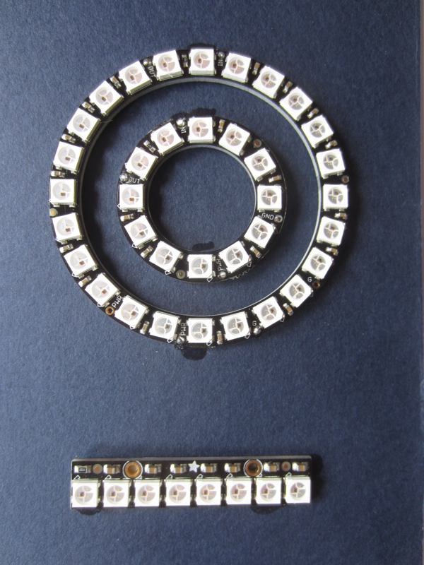
The larger ring has 24 NeoPixels, the smaller has 12 and the strip has 8.

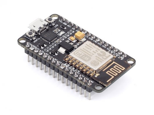
NeoPixels are individually addressable RGB LEDs with built in PWM and serial data controllers.

Back of the frame mat.

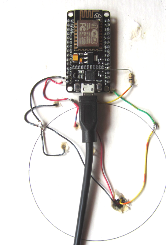
You can see there isn't much to the clock circuit. The Node MCU module was super glued to the mat so it would remain in place while it was connected. As you can clearly see here only three wires connecting the NodeMCU to the NeoPixel devices.

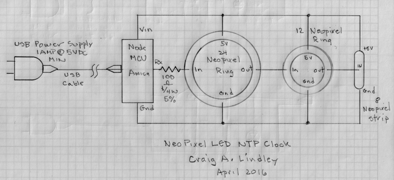
A 100 ohm resistor is placed between the NodeMCU Amica RX output and the input to the large NeoPixel ring to reduce noise on the connection. The output of the large ring connects to the input of the small ring. The output of the small ring drives the input to the NeoPixel strip. The +5V Vin and Gnd connections on the Amica are wired to all three NeoPixel devices.

The clock is powered externally via the USB cable shown and a USB power module of at least 1 amp output current which is not shown.

The following pictures are not that great because the NeoPixels are so bright and the colors so saturated it messes with my camera. In person, the colors are just beautiful.

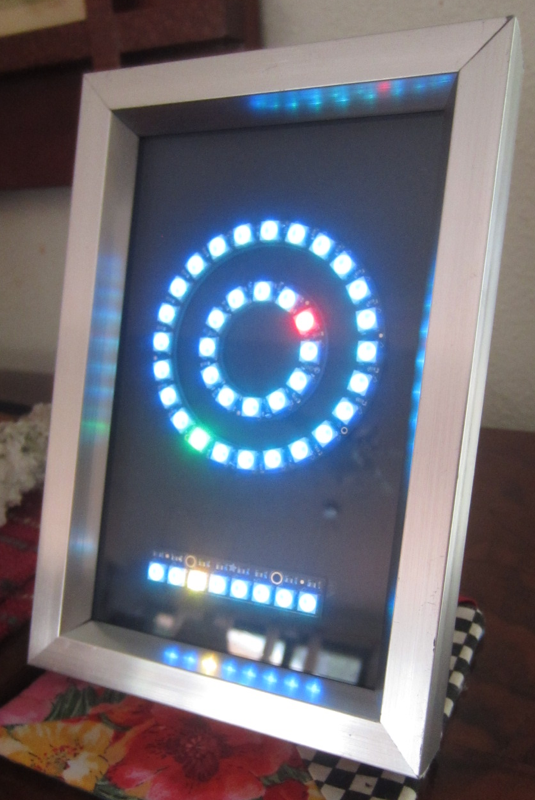
The NeoPixel assembly mounted in a small metal frame makes a nice looking DIY clock.

The firmware reduces the brightness of the NeoPixels otherwise this clock would be blindingly bright.

An image of the 10 minute event. Every 10 minutes the display of time ceases and the NeoPixels display a rainbow of colors that move across all of the LEDs.

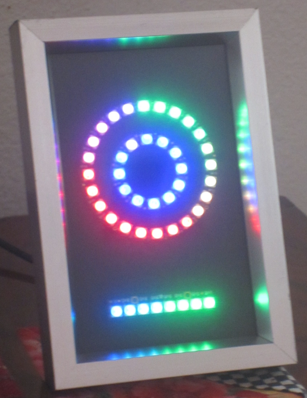
There is also a 15 minute event which flashes colors across all of the pixels.

The 30 minute event displays the current date using the large ring with each component of the date displayed in a different color. First up, the day of the week is displayed on the LEDs with Sunday being the first day. Next the month is displayed with January being month one, followed by the day of the month (1..31) and the year minus 2000. This year the year display shows 16. It takes a little practice to read the date from the LEDs but once you are used to it, reading the date is easy.


Schematic of the NeoPixel LED NTP Clock


Have fun building your own NeoPixel LED NTP Clock !

Home                               Craigs Pages                               Heathers Pages