The Light Appliance Page


Home                               Craigs Pages                               Heathers Pages


July 24, 2014

I recently finished a project I call the Light Appliance. Check out the youtube demo video below.


I've written an article for Nuts and Volts Magazine about the Light Appliance which will be published in the October 2014 issue. If you are interested, you can read the article here.


Here is a front view of the light appliance.  The little item on the left side is the IR detector/receiver for remote control. There are 1024 RGB LEDs in this display arranged in a 32x32 matrix. These LED produce bright and pure colors. The brightness is actually toned down in the software otherwise the display would be blinding.

Side view of the light appliance shows that it is approximately 1 1/2" deep and just slightly wider and taller than the display itself.

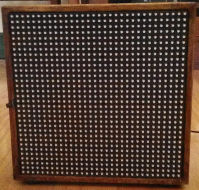
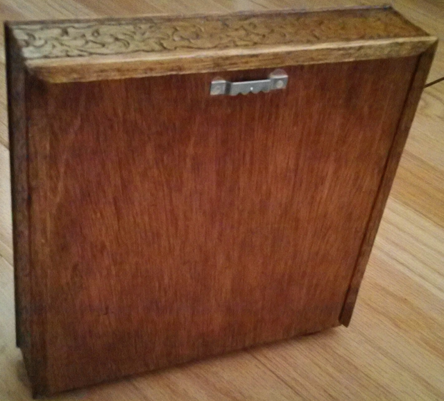
The light appliance can stand on its own  rubber feet or can be hung on a wall.

There are no switches or controls. An IR remote control completely controls this device.

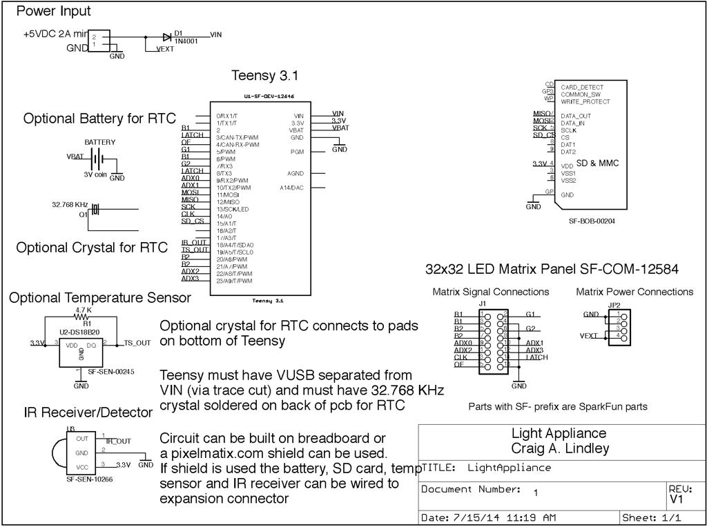
The light appliance is power by an external 5V 2.0A power supply (not shown).

Back view of the light appliance. It has a picture frame bracket for hanging on a wall. The back slides off towards the bottom to allow access to the electronics inside. All in all a neat little package.

This photo show the light appliance with its back slid off. As you can see there isn't much there.

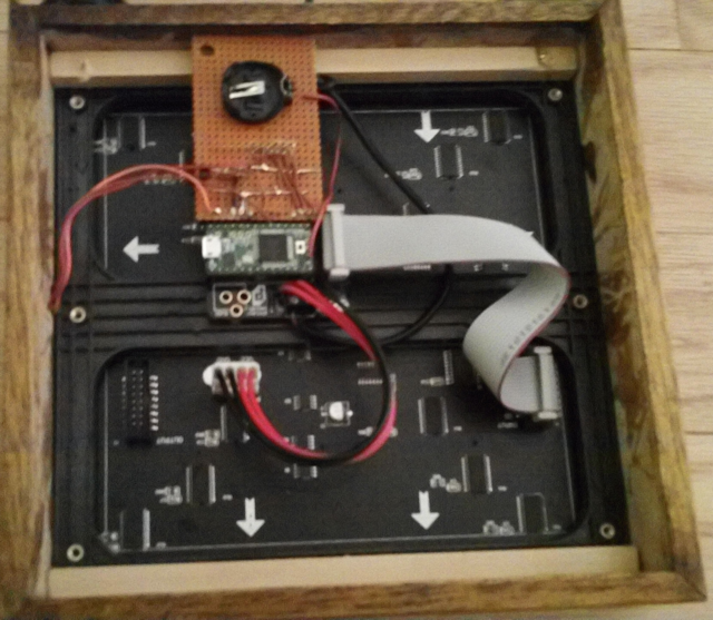
The brown breadboard at the top contains the circuity for the IR detector, the temperature sensor and the RTC backup battery (which is currently missing). Under this breadboard is the SD breakout board for the SD memory card.

The green circuit board is the Teensy 3.1 microcontroller (pjrc.com). The Teensy had the 32 KHz crystal solder onto it as required for the RTC.

The Teensy is plugged into a PCB assembly from pixelmatrix.com which interfaces the Teensy to the underlying 32x32 LED matrix display. Louis Beaudoin of pixelmatrix wrote the display driver on which the light appliance is based.

The gray ribbon cable is for signal connections to the display and the red and black wires are for powering the display. The three wires on the left connect to the IR detector sticking through the front.

Close up of the wood detail. I built this container for the light appliance out of wood from a broken display case I had. It has very nice carvings on it.

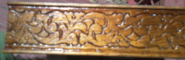
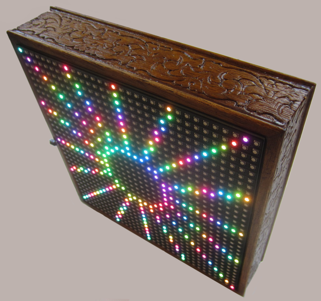
The wood was finished with amber shellac for a nice brown, shiny glow.

The light appliance turned on. Actually it is always on but it has mode which makes it appear to be off. Pressing the Power button on the remote brings up this display.

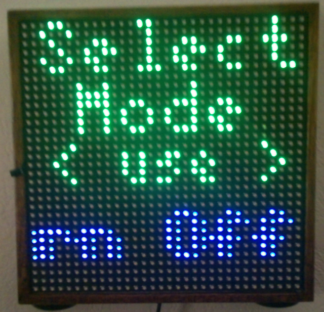
Once on, the light appliance is ready to respond to user requests via the remote.

See the youtube video above for actual operation of the light appliance.

This is the IR remote control used for controlling the light appliance. Simple but effective. It can control the light appliance completely across a good size room.

Schematic of the Light Appliance


All firmware for the Light Appliance is available here.
A collection of animated GIFs for use with the Light Appliance is available here.


Home                               Craigs Pages                               Heathers Pages