December 2019
I needed a new project so I decided to build a six
sided NeoPixel cube. At first I wanted to do this because I
wanted to code up some nice display patterns to show on the
384 pixels which make up the cube but then I thought I could
also show text messages, time and date and the current
weather conditions which would actually make this project
useful (which is always a good thing). So I ended up doing
both; nice patterns and displaying useful information. Because
this project uses the ESP8266 Node MCU module which has
both WiFi and Bluetooth there are many more applications
that the NeoPixel cube could run. If you figure out some
cool new apps for the cube, let me know.
In the current code the cube does the following:
1. Displays a colorful random color pattern which fades to black
2. Displays the following text string: "Welcome to Craig & Heather's"
3. Picks a random display pattern to display from the eight provided.
4. Displays the current time and date: "2:50 pm Fri Dec 20 2019"
5. Picks and displays another random display pattern.
6. Displays the current weather conditions : "Clear 45.6F Wind: 6.3 mph"
7. Picks and displays another random display pattern.
8. Goes to sleep for five minutes and then starts the sequence 1-8 over again.
The display patterns are: rainbow, random pixels, white lightening, random color lightening, theater chase, rainbow theater chase and plasma. Many more could easily be added.
The cube turns itself off from midnight until six in the morning because there would probably be no one around to look at it.
The cube uses NTP time servers for the time data and uses OpenWeatherMap for the weather data. The WiFi manager library is used so that the WiFi network parameters can be set via a web page so the code wouldn't need to change if the cube is moved to a new location.
Currently the cube runs in 12 hour format in the Mountain US timezone (and is daylight savings time aware) and the weather data is displayed for Colorado Springs, CO. USA in emperial units. All of this can be changed, however, because you have access to the Arduino code for the cube. See the link at bottom of the page.
 |
|
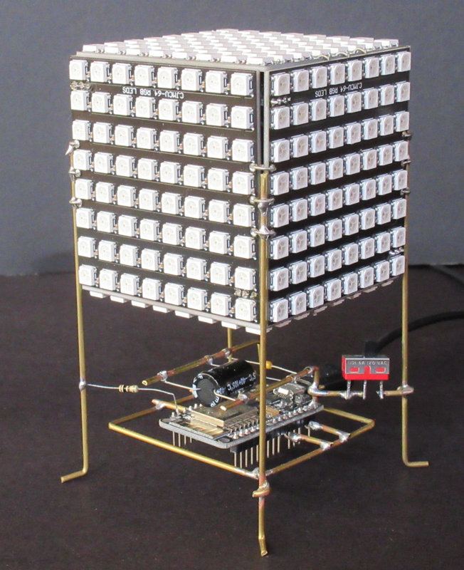 |
Usually I hide the electronics that make up
my projects somewhere inside the project itself but
this time I decided to leave it out in the open so
people can see it. This is currently a popular building technique called "circuit sculpting". All circuit connections are made with 1 mm brass rod/tubing. |
 |
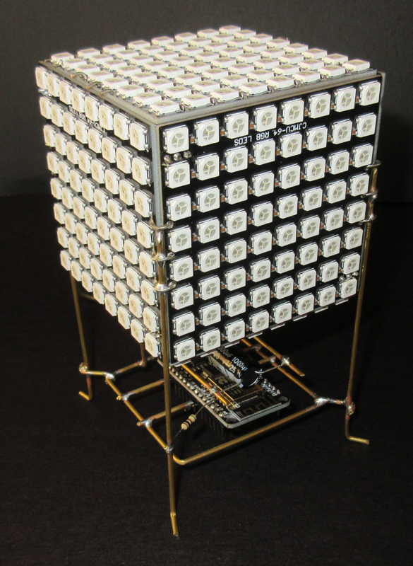
Six 8x8 NeoPixel panels are used to create
the six sided cube. Each panel has a data in, data
out, Vcc or +5 Volts and Ground connection. The panels are wired in the following order: top, front, right side, back, left side and bottom. So the data out of the top panel connects to the data in on the front panel and so on and so on. The circuitry consists of an ESP8266 Node MCU module, three capacitors, a switch and a 100 ohm resistor. See schematic below. The switch controls the power to the cube's NeoPixel panels and is used to power down the panels while the cube is being programmed. Powering down the cube is necessary on my Macbook Pro or else the USB port will turn itself off because of the high power demand. |
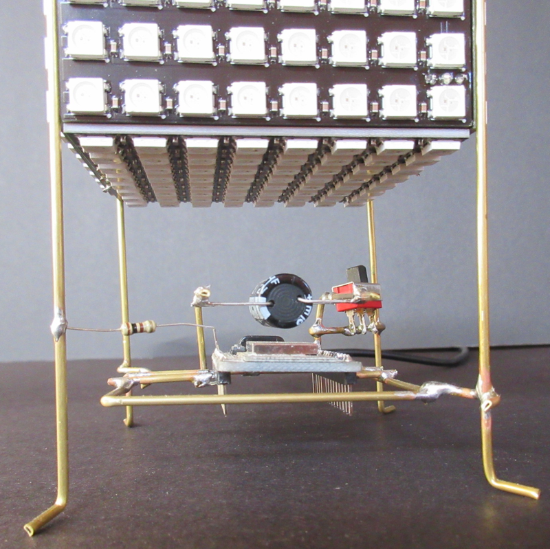 |
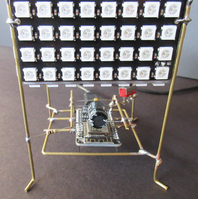
The four legs of the cube are parts of the
circuit. In this image the left front leg is the
connection from the ESP8266 to the data in pin of the
top NeoPixel panel. The 100 ohm resistor is used to
prevent ringing of the data signal caused by the high
data rates. The left rear and right front legs carry the ground connection and the right rear leg is the 5 volt power connection to the cube. The NeoPixel cube is powered by a USB power adapter capable of at least 2 amps. A USB cable connects the USB power adapter to the ESP8266 module. |
 |
Another view of the sculpting. You can see
the WiFi antenna of the ESP8266 Node MCU module in
this view. |
 |
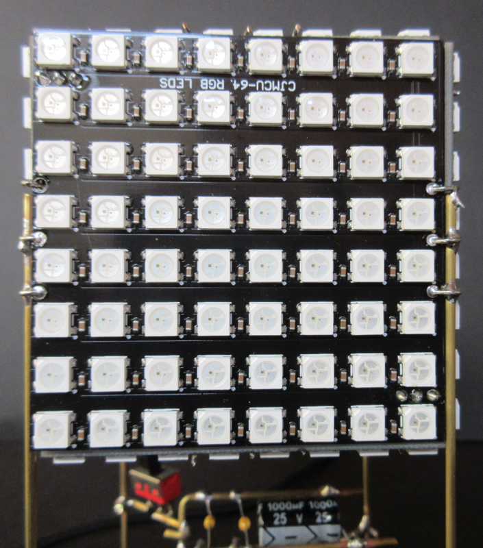
The NeoPixel panels I used each have three
small holes on their left and right sides. To hold the
panels together in the cube I soldered wires between
the panels to which the cube's legs connect. The top
and bottom panels got special treatment because the
side panels don't have holes in the top and bottom. I
glued three wires to the back of the side panels and
ran them through the three holes on both sides of the
top and bottom panels. On the bottom panel these glued
on wires are soldered in place. On the top they are
just bent over so I could remove the top panel if
necessary. I think the NeoPixel Cube turned out nicely and besides being colorful, displays useful messages, time and date and the current weather conditions. |
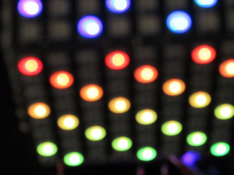
Video is available here.
NOTE: the LEDs are to much for my camera to capture accurately. In person the LEDs are clear and crisp with vivid colors; no washout as seen in the video.
Code for the NeoPixel cube can be found here.
Questions and comments to me Craig at: calhjh@gmail.com