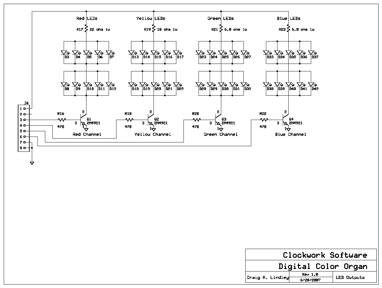
The LEDs are the super bright variety that are bright enough to be seen easily in daylight.
| September 2007 | Floating Point Multiplication and Division without Hardware Support |
| November 2007 | Lattice Wave Digital Filters |
| January 2008 | Psychedelia II - A Digital Color Organ |
|
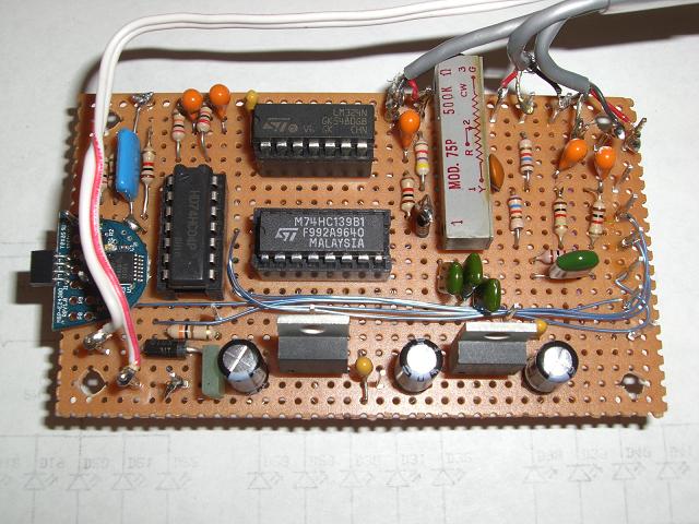
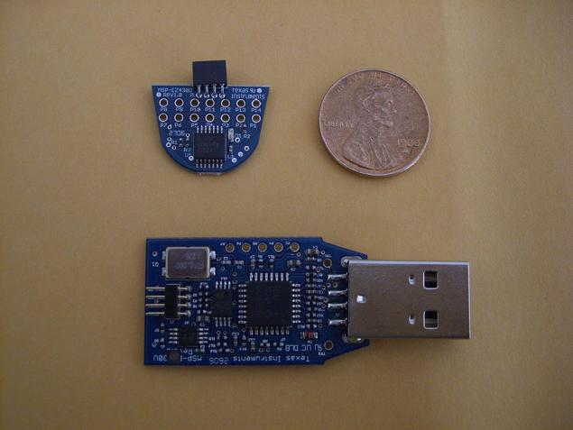
Here is the main color organ
circuitry. The
micro controller which runs the color organ is on the blue board at the
left. |
|
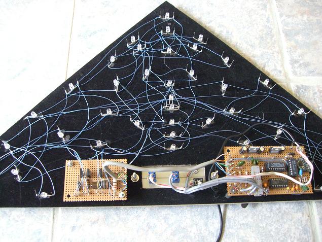
The complete color organ was
built onto the
back panel of a triangular display box I bought at Hobby Lobby. The LEDs are the super bright variety that are bright enough to be seen easily in daylight. |
|
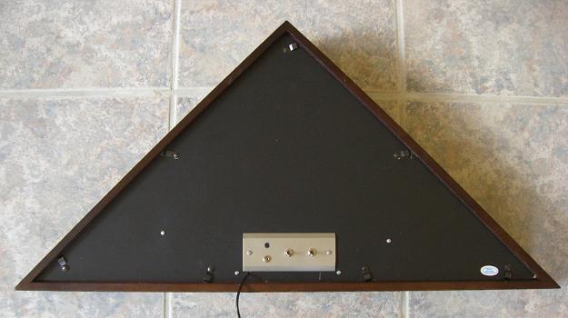
Here is the back of the finished
color
organ. Here you can see the control panel. |
|
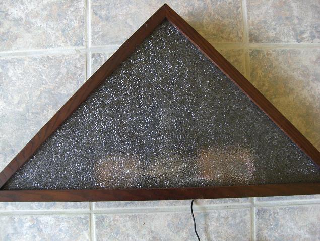
Here is the front of the color
organ. It
turned out nicely I think. |
 |
 |
|
Part Designation |
Value |
Notes |
|---|---|---|
|
C1,C4,C5,C6,C8 |
4.7 uf capacitor |
|
|
C2,C13,C15 |
0.1 uf capacitor |
|
|
C3 |
230 pf capacitor |
|
|
C7 |
0.022uf capacitor |
|
|
C9 |
0.01 uf capacitor |
|
|
C10 |
0.02 uf capacitor |
|
|
C11 |
0.04 uf capacitor |
|
|
C12,C14,C16 |
47 uf capacitor |
polarized |
|
R1 |
4.7 K resistor |
¼ w 5% |
|
R2,R6,R7,R8,R13,R14 |
1 K resistor |
¼ w 5% |
|
R3,R4,R9,R10 |
20 K resistor |
¼ w 5% |
|
R5 |
1 Meg trimmer |
10 or 20 turns |
|
R11,R12 |
1.6 K resistor |
¼ w 5% |
|
R15 |
270 ohm resistor |
¼ w 5% |
|
R16,R18,R20,R22 |
470 ohm resistor |
¼ w 5% |
|
R17 |
22 ohm resistor |
1 w |
|
R19 |
18 ohm |
1 w |
|
R21,R23 |
6.8 ohm |
1 w |
|
D1 |
1N5819 diode |
Optional reverse voltage protection diode |
|
D2,D33-D42 |
Superbrightleds.com Blue LED |
RL5-B4630 |
|
D3-D12 |
Superbrightleds.com Red LED |
RL5-R5015 |
|
D13-D22 |
Superbrightleds.com Yellow LED |
RL5-Y5030 |
|
D23-D32 |
Superbright.com Green LED |
RL5-G5023 |
|
J1 |
Stereo 3.5 mm / 1/8” jax |
Line input connector |
|
J2 |
2 wire power jax |
Optional |
|
J3/J4 |
Inter board connections |
Optional |
|
M1 |
Condenser microphone |
Jameco #160979 |
|
Q1-Q4 |
2N4921 switching/power transistor |
Heat sinks aren't necessary |
|
SW1 |
SPDT |
Mic/line switch |
|
SW2 |
SPST |
Power off/on switch |
|
U2 |
LM2940CT |
5 volt 1 amp voltage regulator |
|
U3 |
LM3940IT |
3.3 volt 1 amp voltage regulator |
|
U4 |
MSP430-F2012 |
uC target
board. Available from TI.com. |
|
U1 |
LM324 |
Quad op amp |
|
U5 |
74HCT139 |
2 to 4 demultiplexer |
|
U6 |
74HCT04 |
Hex inverter/buffer |